

Custom 380V Vibrator Motor Guide for Heavy-Duty Industrial Use
2026-11-16
Most 380V vibrator motors fail early because they're treated as commodity parts. In heavy-duty applications—think mining feeders, aggregate screens, or foundry shakeouts—standard windings and bearings simply can't take the abuse. That's why a custom build from Guangling matters more than you'd expect. This guide breaks down what actually separates a motor that lasts five months from one that runs five years without a teardown.
Sizing Eccentric Force Without Overloading the Drive Shaft
When adding eccentric weights to a vibrating feeder or screen, the drive shaft often becomes the limiting factor before the bearings or housing. A useful starting point is to calculate the bending moment at the bearing shoulder rather than relying on the motor nameplate. The eccentric force increases with the square of the shaft speed, so a small increase in RPM can push a shaft that was previously acceptable into a high-cycle fatigue risk.
One practical approach is to treat the shaft as a simply supported beam with the eccentric mass concentrated at the midpoint. The alternating stress comes from the rotating force vector, not just the static weight of the counterweight. Compare this against the shaft material's endurance limit with a suitable stress concentration factor for the keyway or shoulder fillet. If the margin is too thin, reduce the eccentric radius, increase the shaft diameter, or move the bearing supports closer to the weight.
It is also worth checking the drive-end connection, especially if a V-belt sheave or flexible coupling is mounted outboard. Overhung loads from belt tension combine with the eccentric bending load and can create a peak stress that the simple model misses. In many cases, stepping up one shaft size or switching to a hollow shaft with a larger outside diameter solves the problem without changing the external machine footprint.
Why 380V Custom Windings Beat Rewound Standard Motors
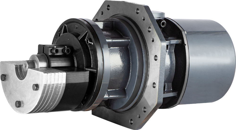
When a standard motor fails, the temptation to rewind it with the original winding data is understandable. It feels economical and straightforward. But for 380V applications, especially in demanding industrial environments, a custom winding designed from scratch often outperforms a simple rewind. The difference lies in how the winding is optimized for the actual operating conditions—not just recreating what was there before.
A rewind typically replicates the original design, including any compromises the manufacturer made for mass production. Custom windings, on the other hand, allow engineers to adjust wire gauge, coil pitch, insulation class, and slot fill to reduce losses, improve thermal performance, and extend insulation life. For 380V motors running on variable frequency drives, custom windings can also mitigate harmonic heating and voltage spike issues that a standard rewind rarely addresses.
The real advantage shows up in longevity and efficiency. Custom windings can be tailored to the specific duty cycle, ambient temperature, and load profile, resulting in lower operating temperatures and better resistance to voltage stress. Rewound standard motors often fail again within a few years under the same conditions. A custom 380V winding, engineered for the application, breaks that cycle and delivers measurable gains in both reliability and energy cost.
Mounting Methods That Reduce Frame Stress in Continuous Duty
Choosing the right mounting configuration isn't just about keeping the motor in place—it's about managing how forces travel through the frame during long, uninterrupted runs. A rigid foot-mounted setup can amplify vibrations and thermal expansion into localized bending moments, especially when the driven load cycles unevenly. By contrast, flange mounts with a spigot or face register distribute reaction forces closer to the shaft centerline, reducing the lever arm that would otherwise twist the frame under torque pulses.
Vertical mounting with a C-face adapter often outperforms horizontal foot mounts in continuous duty because gravity assists rather than fights the bearing alignment. When the motor hangs from a sturdy flange, the stator housing sees primarily axial tension—not the uneven radial loading that foot mounting imposes as the base plate warms and shifts. Adding a resilient ring or a machined pilot fit around the flange shoulder further isolates the frame from driven-equipment misalignment, letting the rotor find its own magnetic center without transferring that fight back into the casting.
For direct-coupled pumps or gearboxes that run around the clock, consider a through-bolt or integral flange design that eliminates separate mounting feet entirely. Without the feet acting as fixed anchors, each thermal cycle doesn't ratchet stress into the stator laminations. And if the application allows, a trunnion or pivot mount with a single axial restraint point can absorb torsional reaction while leaving the frame free to expand longitudinally—turning what would have been fatigue stress into harmless micron-level motion.
Bearing Selection for High Vibration, Low Maintenance Operations
When machinery operates under sustained vibration, conventional bearing choices often fall short—clearances open up, cages crack, and lubricant gets pushed out of the load zone. For these environments, look beyond the standard catalog. Spherical roller bearings with a tighter radial internal clearance (C3 or C4 depending on shaft fit and temperature swing) can absorb misalignment without hammering. But equally important is the cage material: machined brass or polyamide cages withstand cyclic loading better than pressed steel, which tends to fatigue at the rivets. If vibration frequencies are known, avoid ball bearings with deep groove geometry unless they include a vibration-tolerant feature like a snap-ring groove filled with a dampening ring.
Low maintenance doesn't mean no maintenance—it means designing out the frequent re-lubrication and inspection cycles that vibration typically forces on equipment. Solid oil or polymer-filled bearings eliminate grease washout and provide a continuous, micro-porous lubricant supply, which suits sealed gearboxes and conveyor idlers. For high-vibration shafts, consider an adapter sleeve mounting with a hydraulic nut instead of a simple set-screw collar; the 360-degree grip prevents fretting corrosion and loosening. Also, specify contact seals with a secondary dust lip—not non-contact shields—because vibration creates a pumping effect that draws contaminants into the bearing, even with IP65 enclosures.
Finally, look at the bearing housing and surrounding structure. A split plummer block with a heavy cast-iron or ductile iron base provides mass that shifts the natural frequency away from the excitation range. Use a floating bearing arrangement on one side to allow thermal growth without inducing axial preload, which vibration amplifies into spalling. For extreme cases, hybrid ceramic balls with steel rings reduce rotating mass and offer higher stiffness, lowering the amplitude of shaft deflection. Always validate the selection with a simple modal analysis or at least a run-up test—what works in a quiet motor won't necessarily survive a vibrating screen.
Thermal Limits in Sealed Housings Under Heavy Load
Sealed enclosures trap heat in ways open chassis designs never do. Under heavy load, component junction temperatures climb faster than the ambient readings suggest, because there is no forced air path to carry energy away. A sealed aluminum housing might look robust on a spec sheet, but after thirty minutes at full rated current, internal air can sit 25–40°C above the outside temperature. This gap widens further when high-power resistors, magnetics, or MOSFETs are clustered near the enclosure walls.
One practical limit is the thermal time constant of the housing itself. Thick cast walls take time to absorb and re-radiate heat, so early temperature sensors on the PCB may underreport long-term equilibrium. Designers often test with thermocouples on the hottest component body and on the inner wall directly opposite it. If that wall temperature exceeds 85°C, plastic connectors and electrolytic capacitors inside can degrade faster than datasheet lifetime curves predict, especially when load cycles repeat every few minutes.
Derating charts based on open-air ratings mislead when the unit is sealed. A 10W converter rated to 70°C ambient might need to be limited to 6W or 7W once installed in a gasketed enclosure of similar size. The only reliable way to confirm thermal margins is to run the assembly at worst-case load for at least two hours, monitor the hottest internal point, and then check the temperature rise directly on the outer surface. If the exterior stays cool while the interior climbs, the enclosure is not transferring heat effectively, and the load must be reduced or internal conduction paths redesigned.
Tuning Stroke and Frequency for Material Flow Control
Adjusting stroke length alters how far material particles are thrown forward with each vibration cycle. A longer stroke at the same frequency tends to move coarser or denser materials more aggressively, while a shorter stroke gives finer control for fragile or lightweight granules. On many feeders, the stroke is set by changing eccentric weights or adjusting the drive's angular position, and even a millimeter-scale change can shift the flow rate by several percentage points.
Frequency tuning works on the number of impulses delivered per second. Higher frequencies typically produce a smoother, more fluid bed movement and reduce the tendency for bridging or rat-holing in hoppers, but they may also increase noise and component wear. Lower frequencies with a larger stroke often handle heavy, abrasive materials better because each individual throw has more energy. The practical approach is to first fix the frequency that matches the machine's natural resonance or drive constraints, then fine-tune stroke until the discharge rate stays within the target window without excessive bounce-back.
A useful field test is to mark a particle on the tray and time its travel over a fixed distance while adjusting one variable at a time. If the material bunches at the discharge end, reduce stroke slightly or raise frequency to spread the throws. If it barely moves, increase stroke before touching frequency. Recording these settings for different material batches prevents operators from repeating the same trial-and-error sequence after every product changeover.
FAQ
You can specify the excitation force, number of poles, mounting footprint, shaft extension, insulation class, terminal box position, and even special paint or stainless steel hardware. Many heavy-duty jobs also need non-standard frequency, dual voltage taps, or reinforced bearing housings for continuous vibration.
Three-phase power delivers smoother torque with less current per phase, which keeps windings cooler and improves starting under load. In plants where 380V is already available, you also avoid transformer losses and get better efficiency for motors running 24/7 on crushers, screens, or feeders.
Start with the total vibrating mass, including material load, then work from required stroke or amplitude and motor speed. A common rule is to provide 2.5 to 4 times the gravitational force on the trough for heavy-duty use, but you should always leave a 10 to 15 percent margin above calculated value to handle material surges and buildup.
Ask for IP66 sealing, Class H insulation, anti-condensation heaters for standby periods, and bearing seals with a grease relief path. For highly corrosive environments, specify epoxy-coated frames or 316 stainless hardware. Never rely on a standard IP55 motor in a high-moisture, abrasive dust setting.
Yes, but the motor should be inverter-rated and equipped with a separately driven cooling fan if it will run below 30 Hz. Avoid lingering at resonant frequencies of the machine, and program the VFD with a linear voltage/frequency curve up to the rated 380V point to prevent magnetic saturation and overheating.
Foot-mounted motors with reinforced ribs are common, but flange or face mounting reduces flexing on tall hoppers. For wide screens, two motors in a synchronized counter-rotating setup give linear motion and cancel side loads. Always mount on a machined, flat surface and use high-strength bolts with locking washers or thread-locking compound.
The main reasons are inadequate lubrication, axial preload from misalignment, and excessive radial clearance. Use C4 clearance bearings, regrease with the exact interval and quantity from the manufacturer, and monitor vibration spectra. A 10 degree Celsius rise above normal bearing temperature often shows trouble before failure.
Look for IEC 60034 compliance, CE marking, and if the area has combustible dust or gas, ATEX or IECEx certification. For North American installations, ensure the motor is UL or CSA recognized. Also check the efficiency class, usually IE3 or IE4 for continuous heavy-duty operation, and request a test report with locked rotor current and insulation resistance values.
Conclusion
Selecting the right eccentric force on a 380V vibrator motor comes down to balancing the required stroke against the drive shaft's fatigue limit. Oversized counterweights may look like an easy way to boost material movement, but they transfer bending moments straight into the shaft and can shorten bearing life within weeks. A better approach is to start with the bin or chute's natural frequency and calculate the necessary force from the bulk material's angle of repose, not from guesswork. Custom 380V windings matter here because they let you fine-tune the magnetic field strength and slip characteristics for the exact eccentric load, whereas rewinding a standard motor to 380V often leaves you with a rotor that runs hotter and loses torque at the worst possible moment. Mounting the motor on a reinforced steel channel or using a foot-mounted design with dampening bushings spreads the reaction forces and reduces frame stress during continuous duty, especially when the vibrator runs 24/7 on a heavy-duty screen or feeder.
Bearings for high-vibration service need more than a standard C3 clearance. A double-row spherical roller bearing with a machined brass cage handles the axial and radial pounding without fretting the shaft, and adding a grease with extreme-pressure additives extends relubrication intervals even in dusty plants. Sealed housings trap heat, so running a 380V motor at full load inside a compact vibratory table can push winding temperatures past Class F limits if you ignore the internal air gap and rely only on the outer surface for cooling. A practical fix is to specify a lower current density in the custom winding and leave a small ventilation gap between the motor housing and the mounting plate. Finally, tuning stroke and frequency is not about running the motor at maximum RPM. Adjusting the eccentric weight position or using a variable frequency drive lets you match the material's flow characteristics, so fine powders don't fluidize and coarse aggregates don't bridge. This kind of field-tuning, combined with the right mechanical choices, is what separates a reliable heavy-duty installation from one that eats bearings and windings every few months.
Contact Us
Contact Person: ZHUO
Email: [email protected]
Tel/WhatsApp: 86-576-86320988
Website: https://www.cnguangling.com