

Gas Insulated Switchgear Factory: Inside the Manufacturing Process Behind Reliable High-Voltage Systems
2026-08-20
High-voltage power grids don't tolerate failure, yet the engineering behind their most compact and reliable switchgear remains hidden from view. Inside a gas insulated switchgear factory, every sealed chamber, conductor, and insulator is shaped by processes where microns matter. At Lugao, that precision is not an accident—it's built into each stage of manufacturing. This post takes you inside the workflow that turns raw materials into the high-voltage systems utilities count on, revealing what sets a dependable factory apart.
From Raw Casting to Sealed Enclosure
The journey begins with a raw aluminum casting, still rough from the mold and far from ready for service. Machinists face it down with careful setups and patient passes, peeling away excess until the mating surfaces sit flat and true. Threaded holes appear where fasteners will later bite, and small pockets get cleared for seals and connectors. Nothing here is rushed; every cut removes a little more doubt about whether the enclosure will hold its shape under pressure.
Once the machining work settles, the casting moves through a cleaning line that strips away cutting fluid and loose chips. A chemical conversion coating follows, giving the bare metal a thin, dull-gold layer that helps paint adhere and slows down corrosion. Sealing surfaces get masked off before a powder coat bakes on, leaving a finish that resists scratches and shrugs off moisture. The enclosure now looks like a finished product, but it still needs to prove it can keep the outside world out.
Final assembly pulls everything together: gaskets drop into their grooves, connectors thread in with a measured torque, and the lid comes down against a continuous bead of sealant. A quick pressure decay test tells the truth about every seam and fitting. If the needle holds steady, the raw casting has become a sealed enclosure, ready for whatever environment it was meant to face.
Cleanroom Assembly Without Contamination
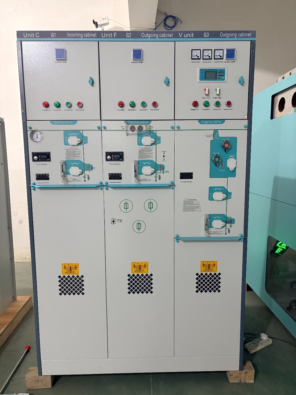
Achieving a contamination-free cleanroom assembly starts long before the first component is unboxed. Every item entering the controlled space passes through a staged decontamination process, and technicians don sterile garments in a specific sequence to avoid trapping particles. The assembly area itself is kept under positive pressure with HEPA-filtered air, which means any leak pushes clean air outward rather than pulling dirty air inward.
During the actual assembly, movement is deliberate and slow. Fast motions create air currents that can dislodge particles from surfaces. Tools are either dedicated to the cleanroom or cleaned with isopropyl alcohol before use, and they rest on lint-free mats instead of directly on workbenches. Components are handled only by their edges or with cleanroom gloves, and any contact with bare skin or non-approved packaging is treated as a contamination event that requires re-cleaning.
Real-time particle counters placed near the assembly station offer immediate feedback. If counts spike above the allowed threshold, work pauses until the source is identified—often a torn glove, an improperly sealed pass-through, or a packaging film that was not wiped down. By treating contamination control as an active, observable process rather than a static checklist, assemblers can maintain the cleanliness levels required for sensitive products like microelectronics or medical devices.
Robotic Welding for Leak-Proof Joints
Achieving a genuinely leak-proof weld has less to do with raw heat and more to do with repeatable torch discipline. Robotic arms bring exactly that: they hold a consistent travel speed, maintain the same work angle across every pass, and never flinch near a corner or a tight fillet. For joints that must hold gas, fuel, or hydraulic fluid, that consistency removes the small underfills and erratic penetration patterns that manual welding often leaves behind.
Modern systems go a step further by tracking the seam in real time. A slight gap change, a tack weld that shifted, or a plate that warped from earlier heat can throw off a fixed program. Adaptive robotic welding measures the joint right before the arc and adjusts wire feed, voltage, and weave width on the fly. The result is a continuous root pass and cap pass with uniform throat thickness, which is what actually prevents pinhole leaks and stress cracks from forming later.
The real payoff shows up in testing. Tanks, exhaust components, and pressure vessels welded this way routinely pass helium leak checks and hydrostatic tests on the first attempt. Instead of grinding out a leaking section and reworking it by hand, manufacturers get a closed joint that holds its integrity through thermal cycling and vibration.
Building the Interrupters That Quench Faults
The core challenge in interrupter design isn't simply splitting contacts; it's forcing the arc to die before it can do damage. For medium-voltage gear, vacuum bottles have become the default because they contain the plasma entirely inside a sealed ceramic shell, leaving nothing to vent or burn. The contact geometry gets less attention but matters just as much: spiral-shaped or contrate cups create a magnetic field that spins the arc root across the surface, preventing any single spot from reaching melt temperature.
Gas-based interrupters take the opposite approach. Instead of starving the arc of particles, they flood the gap with electronegative molecules like sulfur hexafluoride that soak up free electrons. But modern designs rarely rely on a single quenching method. A puffer cylinder compresses gas during the opening stroke and blasts it through the arc at just the right moment, while the nozzle shape determines whether the flow cools the column or simply scatters it. This mechanical timing is where most of the engineering effort goes.
Testing is what separates a working interrupter from one that fails on a cold morning three years later. Manufacturers run short-circuit interruption tests not just to verify the current rating, but to map arc duration against contact wear. Every millisecond of arcing erodes material unevenly, so the contact stroke, spring force, and damping all have to be tuned together. The result is a device that quenches a fault in less than half a cycle, yet still closes reliably after thousands of operations.
Handling SF6 Gas as Invisible Insulation
Sulfur hexafluoride earns its keep in high-voltage switchgear and circuit breakers by quenching arcs and insulating live parts, yet it never announces its presence. Colorless, odorless, and non-flammable, SF6 can leak from a flange or valve without any visible sign, which makes routine handling a matter of trusting instruments over senses. Technicians learn early that a quiet gauge can be more misleading than a noisy alarm, and that standing downwind of a slow leak teaches nothing until a detector starts chirping.
Because the gas is heavier than air, it tends to pool in low spots like cable trenches, pits, and basement entries. Before any inspection or maintenance, those areas need forced ventilation and an oxygen check; otherwise, a worker can step into an invisible layer of SF6 and find the air too thin to support clear thought. Leak hunting itself relies on infrared cameras or electron-capture detectors, not soap bubbles, since the gas escapes through gaps too small to foam. Cylinders should be stored upright in dry, ventilated spaces and never subjected to direct flame or extreme heat, as thermal decomposition creates acidic byproducts that corrode both lungs and metal.
When equipment is decommissioned or serviced, reclaiming the gas beats venting it. A dedicated SF6 recovery cart pulls the gas into a storage cylinder, filters out moisture and breakdown contaminants, and leaves the breaker ready for evacuation and refill. Small residual amounts still hide in adsorbents and oil, so those materials get processed separately rather than tossed into general waste. Handling SF6 well means treating it less like a simple utility gas and more like an invisible partner that demands respect—present but undetectable, critical but unforgiving of shortcuts.
Final High-Voltage Trials That Prove Reliability
Every unit that leaves our floor gets pushed well past its labeled limits—sometimes to the point where a less confident design would arc, trip, or quietly give up. We run repeated impulse tests at voltages that exceed the nameplate rating by a comfortable margin, then hold the equipment under full load while thermal cameras scan for hot spots that don't show up on paper.
The final sequence isn't a single pass/fail moment. It's a battery of interruptions, rapid re-energizations, and short-circuit simulations that mimic the ugliest conditions a substation or industrial feeder can throw at it. Only after a unit survives these runs without insulation breakdown, contact welding, or drift in trip timing do we stamp the serial plate and call it ready.
That kind of abuse testing costs time and a few sacrificed prototypes, but it's the reason our failure rates stay flat even in installations where the grid is anything but stable. When a breaker or switchgear enclosure carries the test report from this final high-voltage trial, it has already proven it can handle the worst day of its service life before the first real customer ever connects a cable to it.
FAQ
Gas insulated switchgear uses sulfur hexafluoride or similar insulating gas under pressure to achieve compact dimensions and high dielectric strength, whereas air insulated switchgear relies on atmospheric air and requires much larger clearances. In a factory setting, this means every sealed compartment must be machined and assembled to hold gas without leaks, which drives tighter tolerances and more rigorous testing.
Enclosures are typically welded from aluminum alloy or stainless steel using automated orbital welding or robotic MIG processes. After welding, each enclosure undergoes helium leak testing and sometimes X-ray inspection of weld seams. Machined flanges and O-ring grooves are held to micron-level flatness to ensure the sealing faces compress evenly when bolted together.
During final assembly, internal components like conductors, insulators, and contact systems must be free of particles, moisture, and oil residues. Factories use positive-pressure cleanrooms with HEPA filtration, operators wear lint-free garments, and parts are cleaned with ultrasonic baths or vapor degreasing before entering the assembly area. This prevents partial discharge caused by contaminants trapped inside the gas compartments.
The gas compartments are evacuated to remove air and moisture, then filled with SF6 or an alternative gas mixture to a specified pressure. Automated gas handling carts measure dew point and gas purity during filling. After sealing, each compartment is checked with a gas density monitor and a sensitive leak detector, often using a sniffing probe or accumulation chamber, to confirm the leak rate stays below the design limit.
A completed bay undergoes routine tests including power frequency withstand voltage, lightning impulse voltage, partial discharge measurement, and circuit breaker timing and travel tests. Mechanical endurance tests may simulate hundreds of operations on disconnectors and earthing switches. The gas system is verified for alarm and lockout thresholds, and all interlocks are checked to prevent unsafe operations.
Internal conductors are supported by cast resin insulators that are precisely machined to locate the conductor relative to the enclosure. Assembly jigs and laser alignment tools hold the parts during insertion. For complex three-phase enclosures, factories use 3D coordinate measuring machines to verify that contact gaps and creepage distances meet design drawings before the compartment is closed and filled with gas.
Modern gas insulated switchgear factories employ closed-loop gas handling systems that recover, filter, and reuse SF6 rather than venting it. Leak detection is performed at every stage, and any gas removed during testing is stored in dedicated pressure vessels. Some manufacturers also offer alternative gas mixtures with lower global warming potential, and these require adapted filling and test procedures.
Beyond routine tests, manufacturers perform type tests on prototype designs, including temperature rise tests, short-circuit withstand tests, and accelerated aging tests on seals and insulators. Long-term reliability is also supported by factory audits of material suppliers, traceability of every critical component, and periodic destructive teardown of sample units to inspect for hidden degradation after simulated service conditions.
Conclusion
Inside a gas insulated switchgear plant, the journey begins with raw aluminum castings that are machined, honed, and pressure-tested before they earn a place in the sealed enclosure. Cleanroom assembly is not a luxury but a necessity: a single particle trapped inside can trigger a flashover under high voltage. Technicians in full suits handle components under laminar airflow, while robotic welding stations lay down continuous, perfectly controlled beads around flange joints. Every weld is then checked with helium leak detection—far more sensitive than soap bubbles—so that the final enclosure can hold SF6 gas at pressure for decades without a whisper of leakage.
The heart of the switchgear, the interrupter, is assembled with moving and fixed contacts aligned to hair-thin tolerances, because this is the part that must extinguish an arc before it becomes a fault. SF6 gas is treated as both an invisible insulator and a delicate chemical: it is filtered, dried, and filled under precise vacuum cycles to remove moisture and air. Only after all assemblies pass partial discharge and high-potential tests—some at voltages well above the rated level—does the switchgear leave the factory. These final trials, including lightning impulse tests and temperature-rise runs, are what separate a reliable high-voltage system from an expensive gamble.
Contact Us
Contact Person: Doreen
Email: [email protected]
Tel/WhatsApp: 8618057712366
Website: https://www.liugaopower.com/