
Shredder Fabrication: Essential Techniques for Durable Builds
2026-08-17
Building a shredder that withstands daily abuse demands more than just welded steel—it requires a deep understanding of stress distribution, material selection, and precision fabrication. At Shengzhong Shredder, we've spent years refining these techniques to ensure every unit delivers unmatched longevity. In this post, we'll explore the core methods behind our durable builds, from frame reinforcement to blade hardening, and why they matter for your operation.
Choosing Steel That Won’t Fold Under Pressure
Steel that folds under load usually fails long before it breaks. Start with yield strength, but treat it as a floor, not a ceiling. A material can show impressive yield numbers on a spec sheet and still crack because its elongation is poor or its toughness drops sharply at the temperatures you actually work in. The useful question is not just "how strong is it?" but "what does it do after it starts to move?"
Pay close attention to how the grade behaves in the condition you'll buy it. Quenched and tempered alloys often hold their shape better than ordinary carbon steel at the same hardness, especially when the load cycles or reverses. If the part gets welded, look at the heat-affected zone properties as much as the base metal. A low carbon equivalent and a tested impact value at your lowest service temperature will do more to prevent sudden folding than a slightly higher yield rating.
Dimensions and support conditions matter just as much as chemistry. A thinner plate in a higher grade can buckle before a thicker, lower-grade piece because stiffness depends on section shape, not just strength. Ask for mill certs from the same heat and thickness you're actually ordering, and compare the reported yield and elongation against your worst-case load, not the average.
Weld Patterns That Outlast the Machine
A weld bead isn't just a line of molten metal—it's a fingerprint of the process that made it. The tight, even ripples of a TIG pass on stainless steel tell you about heat control and patience. The uniform drag lines of a submerged arc weld on heavy plate speak to deep penetration and steady travel speed. These patterns don't form by accident. They're shaped by the welder's hand, the machine's settings, and the joint's geometry. When a component sees years of thermal cycling, vibration, or load reversal, the weld pattern becomes the first thing to inspect. A smooth, consistent toe angle and a gradual transition to the base metal aren't just aesthetics; they're stress risers kept in check.
Most machines fail long before the weld does—if the weld was laid down with an eye toward fatigue life. On a mining truck's A-arm or a pump casing in a refinery, the difference between a weld that lasts 20,000 hours and one that cracks at 5,000 often comes down to pattern discipline. Engineers talk about 'weld toe grinding' or 'capping passes' like they're rituals, and in a way they are. Each ripple, each overlap, each stop-start point is a record of the arc's journey. When you see a weld that outlasts the machine, you're usually looking at a pattern that was deliberately planned, not just deposited.
The old hands will tell you: the arc doesn't lie. A weave too wide, a travel speed too fast, a filler rod fed in a panic—those show up later as undercut, porosity, or a lumpy cap that invites cracks. But a pattern that stays uniform under magnification, with a fine scale and a consistent wash into the parent metal, that's a weld that's already paid its dues. It's the kind of pattern you'll find on a 40-year-old tractor frame still pulling stumps, or on a pressure vessel that's been through 100,000 cycles. The machine may be on its third engine, but the weld hasn't moved.
Heat Treating Blades for Edge Retention
Getting a blade to hold a keen edge isn't just about the steel you pick—it's about how you treat it. Most makers focus on hardness, but edge retention depends just as much on the balance between carbide structure and matrix toughness. If you over-soak at austenitizing temperature, you'll dissolve too many carbides and lose that fine, wear-resistant edge. Under-soak, and you leave soft spots that roll over the moment they touch wood or rope. The sweet spot is usually a lower austenitizing range for high-alloy steels, paired with a fast quench that locks in a fine grain.
Tempering is where many heat treatment recipes go wrong. It's tempting to do a single high-temp temper for convenience, but that often leaves retained austenite and uneven hardness. For edge stability, a double or triple temper at a moderate temperature—around 300–350°F for many stainless steels—converts most retained austenite without sacrificing too much hardness. Let the blade cool fully between tempers, and don't rush. The goal isn't just hitting HRC 60 or 61; it's making sure the very apex of the edge stays stable under repeated loading.
Sub-zero treatment used to be optional, but for high-alloy steels it makes a real difference. A quick dip in dry ice or liquid nitrogen after the quench and before tempering pushes retained austenite to transform into martensite. That adds a few points of hardness right at the edge and reduces micro-chipping during hard use. Pair that with a careful normalization cycle before hardening, and you end up with a blade that cuts longer—not because the steel is exotic, but because every step of the heat treatment was controlled with edge retention in mind.
Balancing the Rotor to Kill Vibration
Most rotor vibration problems trace back to a simple fact: the mass center rarely lines up with the axis of rotation. Even a few grams of asymmetry at operating speed can generate forces strong enough to shake bearings loose and crack support structures. The first step is always to measure, not guess. Vibration analyzers with phase references let you pinpoint the heavy spot and calculate the exact correction weight needed at a chosen radius.
After the initial run, mark the shaft, add a trial weight at a known angle, and record how the amplitude and phase shift. This data feeds a vector calculation that tells you where to place the final correction—or where to remove material. On flexible rotors, the balance may hold perfectly at one speed but fall apart at another, so a second trim run near the critical speed often makes the difference between acceptable and dead smooth.
Reinforcing the Housing Against Fatigue
Fatigue failures in housing structures rarely start at the midpoint of a flat wall. They begin at sharp corners, abrupt section changes, or around bolt holes where cyclic loads amplify local stress. Reinforcing the housing against fatigue means first mapping those high-risk zones, then adding material where it actually matters—thicker ribs across load paths, generous fillets instead of sharp notches, and reinforcing bosses around fasteners. Simply thickening every wall adds weight without addressing the root cause, so the reinforcement has to follow the stress flow rather than blanket the entire casting.
Cast iron and aluminum housings both benefit from controlled cooling and shot peening, but the biggest gains come from design changes that lower the stress range. Adding ribs along the direction of principal stress, reorienting bolt patterns to reduce prying, and smoothing transitions between flanges and walls can double the fatigue life without changing the base material. For housings that see repeated tension-compression cycles, local compressive residual stress from peening or rolling near fillets can delay crack initiation. The goal isn't just stronger housing; it's a housing that handles millions of load cycles without developing a single crack.
Designing Service Points Into the Frame
When a service point is treated as an afterthought, it often ends up as a bolt-on module that disrupts the visual and functional rhythm of the frame. Designing it into the frame from the start means considering the point not as a separate component, but as an integral part of the load path and aesthetic geometry. This might involve recessing a fixture within a beam, routing conduits through hollow sections, or shaping a joint so that the service connection becomes a deliberate visual accent rather than a necessary intrusion.
The practical benefits go beyond appearance. By aligning service points with the frame's natural stress distribution, you avoid creating weak spots or requiring additional reinforcement. A well-integrated service point can also simplify installation and maintenance, because access panels and connection points are positioned where the frame already has logical breaks or junctions. This approach demands early coordination between structural engineers, service designers, and fabricators, but the result is a cleaner, more durable assembly where every element has a reason for being where it is.
One effective strategy is to use the frame's modularity to your advantage. If the frame is built from repeated units, designate specific units as 'service nodes' and design their internal geometry to accommodate pipes, cables, or mounting hardware without altering the external profile. This keeps the overall frame appearance consistent while embedding functionality exactly where it's needed. The key is to make the service point feel inevitable—something that belongs to the frame's logic, not a compromise forced upon it.
FAQ
Abrasion-resistant steel like AR400 or Hardox for the housing and rotor plates works well. Mild steel is fine for a base but warps quickly under continuous impact. For blades, D2 or A2 tool steel holds an edge far longer than standard carbon steel.
Preheat thick sections to around 250 to 300 degrees Fahrenheit before welding, then let the assembly cool slowly under an insulating blanket. Peening each pass while it is still warm also relieves shrinkage stress that leads to cracks.
A rotor that is even a few thousandths out of line will chew through bearings and produce vibration that loosens bolts. Use a dial indicator on the bearing seats before final welding, and recheck after any stress-relief heat treatment.
Set the shaft on two level, low-friction rails and let the heavy side roll to the bottom. Add or remove material at the blade mounting points until it no longer has a preferred resting position. Balance each blade stack before assembly to save time.
Calculate the cutting force from the thickest material you expect, then add at least 30 percent overhead. A hydraulic motor with a pressure relief valve works better than a direct electric drive because it can slip instead of snapping shafts when something jams.
A hooked, positive-rake tooth profile grabs and pulls material in, but it can snag on thin metal. For mixed scrap, use a lower rake angle around 5 to 10 degrees with wider gullets and staggered teeth, so the blades shear rather than tear.
Line high-impact zones with replaceable wear plates, either UHMW polyethylene for low-friction flow or ceramic tiles for abrasive grit. Bolt them in from the outside so you can swap plates without cutting into the main structure.
Check blade-to-bed clearance weekly, and listen for changes in running pitch since they usually show up before visible wear. Keep a log of motor current draw because a gradual rise often means dull blades are loading the drive more.
Conclusion
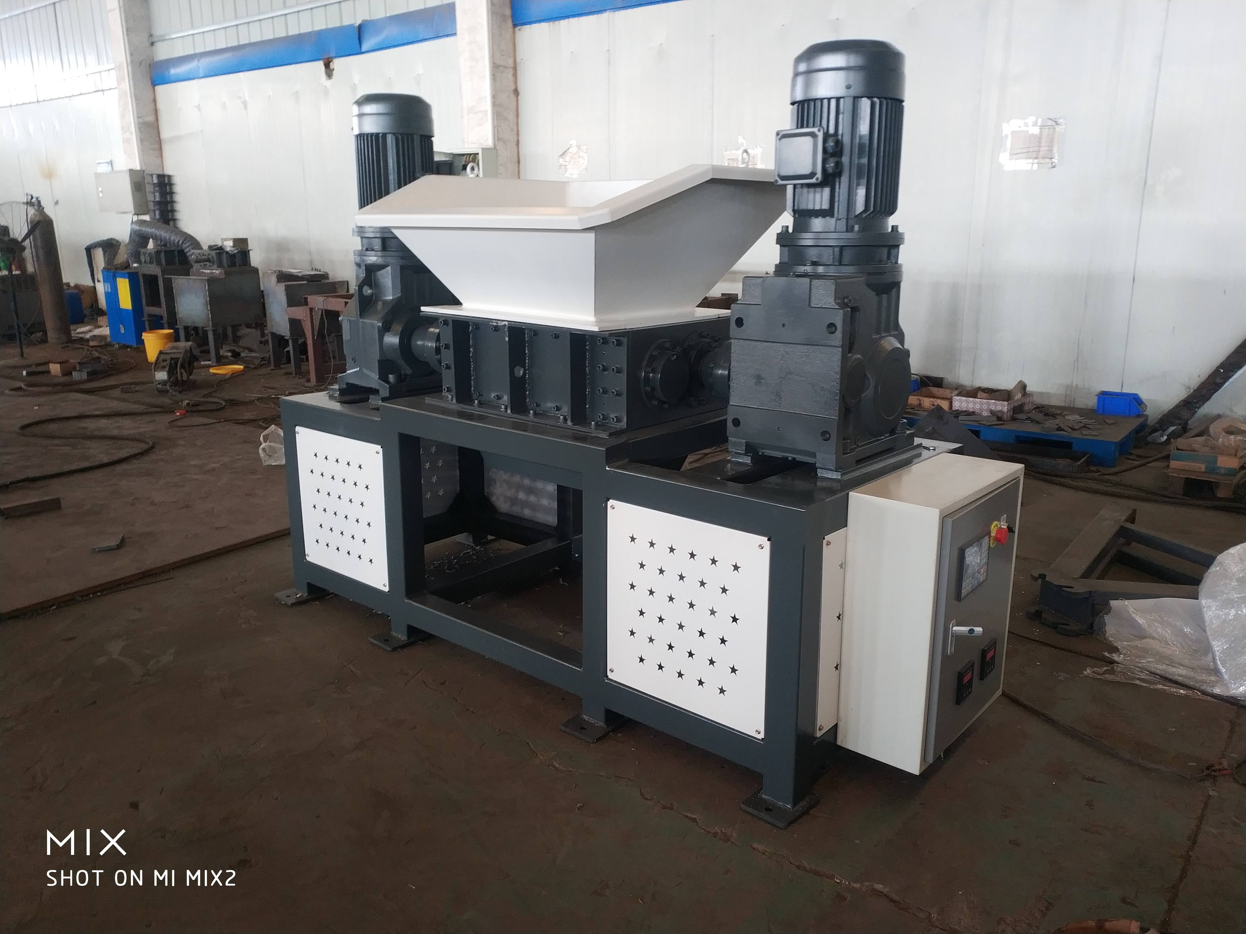
Durable shredder builds start long before the first weld, with steel selection that prioritizes yield strength over hardness alone. A tough, medium-carbon alloy resists deformation under impact loads, while careful control of sulfur and phosphorus keeps the grain structure clean and less prone to cracking. Once the right plate is on the bench, weld sequencing becomes the next failure point. Staggered, short passes with a preheated base metal reduce residual stress, and full-penetration joints at high-load intersections prevent the kind of fatigue fractures that show up after a few thousand cycles. Blades get their edge retention from a tailored heat treatment, typically an austenitizing soak followed by an oil quench and a double temper. This leaves the cutting edges hard enough to stay sharp but tough enough to absorb hits from tramp metal.
A shredder that shakes itself apart is a design failure, not an operator error. Rotor balancing is non-negotiable; dynamic balancing on a dedicated machine corrects both static and couple unbalance, which kills vibration at the source instead of masking it with dampers. The housing needs the same attention. Adding gussets at corners, using continuous fillet welds on high-stress seams, and incorporating a slight crown on large flat panels prevents oil-canning and crack propagation. Finally, service points should be built into the frame, not bolted on as an afterthought. Bolt-on access panels, replaceable wear liners, and lifting lugs positioned at the center of gravity make routine maintenance faster and reduce the chance of collateral damage during teardown. These techniques together produce a machine that holds its tolerances and keeps cutting long after cheaper builds have failed.
Contact Us
Contact Person: Leon
Email: [email protected]
Tel/WhatsApp: 8615385558866
Website: https://www.shred-waste.com